Saturday, September 5, 2015

A Close Look at the Redistribution of OSPF Routes into BGP in the ProCurve

As an example, consider the following network diagram:


OSPF Area 0 includes switches SW1, SW3 and SW4. In SW3, a static route to network 10.8.0.0/16 is configured, and this static route is configured to be redistributed into OSPF. Also in SW3, subnet 192.168.13.0/24 (or VLAN 13) is connected and also configured to be redistributed into OSPF.

We will focus on SW1, where both OSPF and BGP are configured, and where OSPF routes are exported into BGP.

First, the routing table in SW1 will look like this:


Notice that SW1 learned 3 routes from OSPF:

- 10.12.30.0/24 (VLAN 30) generated from with OSPF, hence listed here as "IntrArea" and considered an internal route.
- 10.8.0.0/16 and 192.168.13.0/24 (VLAN 13) distributed into OSPF from "static" and "connected", hence listed here as "External2" and considered external routes.

Now let's look at the distribution of these OSPF routes into BGP in SW1. Below is how SW1 is configured under BGP router (Scenario 1):

router bgp 1200
    enable
    redistribute ospf
    neighbor 192.168.20.2 remote-as 1300
    exit


With the above configuration, the BGP routing table in SW1 will look like:


As seen in the screenshot above, only the OSPF route 10.12.30.0/24 appeared in the BGP routing table. The reason is that the command "redistribute ospf" under BGP only exports OSPF internal routes into BGP. All external routes are excluded from the redistribution.

Now consider another BGP configuration in SW1 (Senario 2):

router bgp 1200
    enable
    network 10.8.0.0 255.255.0.0
    redistribute ospf
    neighbor 192.168.20.2 remote-as 1300
    exit


In this configuration, under BGP we have the command "network 10.8.0.0 255.255.0.0". The resulting BGP routing table will looks like:


In the screenshot above, in addition to the OSPF internal route of 10.12.30.0/24 (VLAN 30) which is exported into BGP by the command redistribute ospf, the route to subnet 10.8.0.0/16 also appears in the BGP table because in this scenario we have the command network 10.8.0.0 255.255.0.0 under BGP. In contrast, a route to subnet 192.168.13.0/24 (VLAN 13) is not present in the BGP routing table because this subnet is not configured with the network command under BGP.

The bottom line is that in the ProCurve, OSPF external routes cannot be exported into BGP using the redistribute command. They have to be specified using the network command under BGP to be present in the BGP routing table. This is different from Cisco IOS, which allows the export of OSPF external routes into BGP by the command redistribute ospf 1 match external.

Thursday, September 3, 2015

Configuring and Monitoring Policy-based Routing (PBR) in the ProCurve

(This feature is available only on the 3800 Series, and the 5400/8200 Series with v2 or higher modules)

PBR allows path manipulation based on packet attributes. The following steps are required to configure PBR:

- Traffic is selected into one or more classes by using the “match” and “ignore” commands.
- A PBR policy is created, which specifies the actions to be performed on a traffic class.
- The policy is then applied to inbound traffic on a VLAN interface. PBR cannot be applied to a physical port.

Creating a class:

HP-5406zl(config)# class ipv4 Windward
HP-5406zl(config-class)# match tcp 192.168.4.0/24 eq 9801 host 192.168.1.3
HP-5406zl(config-class)# exit

In the example above, a class named "Windward" was created for all TCP traffic with the IP source address belonging to subnet 192.168.4.0/24, TCP port 9801, and destination address 192.168.1.3. For verification, use the command “show class config”. The “match” command accepts a wide range of protocols (tcp, udp, ip, igmp, esp, ospf, pim, and so on). Under each protocol we can specify source/destination IP addresses, TCP/UDP ports, DSCP, VLAN, etc. Use the question mark (?) in the CLI to view the available options.

Creating a PBR policy:

HP-5406zl(config)# policy pbr Alpharetta
HP-5406zl(policy-pbr)# class ipv4 Windward
HP-5406zl(policy-pbr-class)# action ip next-hop 20.0.0.1
HP-5406zl(policy-pbr-class)# exit

In the example above, a PBR policy named "Alpharetta" was created for the traffic class Windward as defined in the previous part. All packets matching the class Windward will have IP address 20.0.0.1 as the next hop. PBR actions also include “interface null”, which will drop the applicable packets. Each class may include up to 8 actions; the first action will be executed first, and the next action will apply if the first action cannot be executed (for example, the specified interface in the first action is down). Using this feature, multiple backup routes can be configured for a class of traffic.

Applying the PBR policy to a VLAN interface:

HP-5406zl(config)# vlan 10
HP-5406zl(vlan-10)# service-policy Alpharetta in

Notice that PBR policies only apply to VLAN interfaces, and only in the inbound direction.

Monitoring PBR:

The show statistics policy command displays hit counts for each policy action.

To enable debug logging for PBR, enter the debug ip pbr command.

Monday, July 20, 2015

Link Aggregation between ProCurve and Comware Switches

Suppose we want to do link aggregation between ports A1-A2 on the ProCurve 5400 side and ports GigabitEthernet 1/0/1 and 1/0/2 on the Comware 5900 side, with all VLANs permitted  and VLAN 100 as the untagged VLAN on the aggregated link. We can configure a static non-protocol link aggregation or a static LACP link aggregation as described below:

1. Configuring a static, non-protocol link aggregation:

On the 5900 Comware side, enter the following commands in system view mode:

interface bridge-aggregation 1
port link-type trunk
port trunk permit vlan all
port trunk pvid vlan 100
quit

interface gigabitethernet 1/0/1
port link-aggregation group 1
quit

interface gigabitethernet 1/0/2
port link-aggregation group 1
quit


On the ProCurve 5400 side, enter the following command in configuration mode:

trunk a1-a2 trk1 trunk

Also the interface trk1 must be untagged for VLAN 100 and tagged for all other VLANs.

For verification, issue the command display link-aggregation verbose in the Comware switch and show trunk in the ProCurve switch.

2. Configuring a static LACP link aggregation:

On the 5900 Comware side, enter the following commands in system view mode:

interface bridge-aggregation 1
port link-type trunk
port trunk permit vlan all
port trunk pvid vlan 100
link-aggregation mode dynamic
quit

interface gigabitethernet 1/0/1
port link-aggregation group 1
quit

interface gigabitethernet 1/0/2
port link-aggregation group 1
quit


On the ProCurve 5400 side, enter the following command in configuration mode:

trunk a1-a2 trk1 lacp

Also the interface trk1 must be untagged for VLAN 100 and tagged for all other VLANs.

For verification, issue the command display link-aggregation verbose in the Comware switch and show lacp in the ProCurve switch.

Tuesday, June 2, 2015

Distributed Trunking in HP ProCurve Switches

Distributed Trunking allows the aggregation of links from one device to two upstream switches. To the downstream device, the two upstream switches appear to be just one single switch.


In the figure above, a trunk (or if you prefer, an aggregated link) named Trk2 is formed from two links, the first link going from Port 1 in Switch 3 to Port A2 in Switch 1, the second one going from Port 2 in Switch 3 to Port A2 in Switch 2. So instead of link aggregation between 2 switches, here we have link aggregation between 1 switch and 2 others. Hence the name "Distributed Trunking".

To the downstream switch, i.e. Switch 3, the two upstream switches (i.e. Switch 1 and Switch 2) appear just like one single switch. This is made possible by the ISC (Inter-switch Connection) between Switch 1 and Switch 2. Switch 1 and Switch 2 must be of the same model and running the exactly same software version for the ISC to work. The ISC could be a single link, or an aggregated link as shown in the example figure above (Trk1).

The keepalive link helps monitoring the status of the ISC. It must be in a separate, non-default VLAN with ports dedicated just for that purpose. No data or synchronization traffic is sent over the keepalive link, so it is not essential to the operation of Distributed Trunking.

Here's how to configure Distributed Trunking using the example in the figure above. Besides LACP, static non-ptotocol trunks can be used as well.

In Switch 1:

trunk A1,A3 trk1 lacp
trunk A2 trk2 dt-lacp
switch-interconnect trk1

vlan 1024
     untag A4
     ip address 192.168.124.1/24
distributed-trunking peer-keepalive vlan 1024
distributed-trunking peer-keepalive destination 192.168.124.2


In Switch 2:

trunk A1,A3 trk1 lacp
trunk A2 trk2 dt-lacp
switch-interconnect trk1

vlan 1024
     untag A4
     ip address 192.168.124.2/24
distributed-trunking peer-keepalive vlan 1024
distributed-trunking peer-keepalive destination 192.168.124.1


In Switch 3:

trunk 1-2 trk2 lacp

For verification, run the command show lacp distributed. The output will look like below:


Certain network features are not supported when Distributed Trunking is configured. As of K/KA/KB.15.16:

- ARP Protection is not supported on the distributed trunks.
- Dynamic IP Lockdown Protection is not supported on the distributed trunks.
- QinQ in mixed mode is not supported.
- Meshing is not supported.
- Multicast routing is not supported.
- IPv6 routing is not supported.

Thursday, May 28, 2015

Smart Link in ProCurve Switches

Smart Link provides link redundancy using dual uplinks between different layers of the network, such as between the access layer and the distribution layer as shown in the figure below.


In this type of scenario Smart Link can be used in place of STP for faster convergence. Normally only the primary connection is active. When the primary connection is down, the backup connection will carry the traffic. This arrangement can be used for load sharing as well, in which case one link is configured as primary for a group of VLANs and the other link as primary for another group of VLANs (similar to MTSP instances).

Below is an example on how to configure Smart Link with VLAN load sharing. VLANs 1-10 are mapped to Smart Link group 1, while VLANs 11-20 are mapped to Smart Link group 2. The "role" option that follows "preemptive-mode" indicates that a Master port will take over as Master (for a group) after it comes back up from a failure.

smart-link group 1 master a1 slave a2
smart-link group 1 protected-vlans 1-10
smart-link group 1 send-control-vlan 1
smart-link group 1 preemption-mode role
smart-link group 1 preemption-delay 10

smart-link group 2 master a2 slave a1
smart-link group 2 protected-vlans 11-20
smart-link group 2 send-control-vlan 11
smart-link group 2 preemption-mode role
smart-link group 2 preemption-delay 10


To view Smart Link configuration and status, use the show smart-link commands.

Thursday, April 30, 2015

Dynamic ARP Protection in HP ProCurve Switches

Dynamic ARP protection is designed for defense against ARP spoofing attacks, which take advantage of gratuitous ARP replies to falsify IP-to-MAC bindings in network devices. Here's how it works:

- On ports not configured as "trusted" (by default all ports are "untrusted"), all ARP requests and responses are intercepted.
- The IP-to-MAC bindings in intercepted ARP messages are verified against the DHCP snooping binding database (including user-configured static bindings).
- If a binding is valid, the switch will use it to update its local ARP cache and forward the packet. Otherwise the packet containing that binding will be dropped.

Because of the binding validation against the DHCP snooping database, DHCP snooping has to be enabled for ARP protection to work. If DHCP snooping is not enabled, valid ARP traffic will be dropped.

Here's how to configure dynamic ARP protection:

HP-5406zl(config)# dhcp-snooping
HP-5406zl(config)# arp-protect
HP-5406zl(config)# arp-protect trust B1 (configuring port B1 as trusted)
HP-5406zl(config)# arp-protect vlan 1-2 (configuring ARP protect for VLANs 1 and 2)
HP-5406zl(config)# arp-protect validate dest-mac

The last command is optional. The option "dest-mac" means that the switch will drop any ARP response packet in which the destination MAC address in the Ethernet header does not match the target MAC address in the body of the packet. Other options are "src-mac" (drop any ARP request or response packet in which the source MAC in the Ethernet header does not match the sender MAC address in the body of the packet) and "ip" (drop any ARP request or reply with an invalid IP address - 0.0.0.0, 255.255.255.255, all IP multicast addresses and all class E IP addresses).

To verify and monitor/troubleshoot dynamic ARP protection, the following commands are available:

show arp-protect
show arp-protect statistics 1-2 (statistics for VLANs 1 and 2)
debug arp-protect

For example, the output of "show arp-protect" will look like below:


Lastly, to add static IP-to-MAC bindings to the DHCP snooping binding database, use the command ip source-binding in the global context.

Tuesday, April 28, 2015

Creating and Using Route Maps in ProCurve Switches

Creating route maps:

A route map consists of “match” statements to select the routes for the intended policy. Optionally, “set” statements can be included to modify route properties. Optional prefix lists can also be configured to select routes for the "match" statements.

Prefix lists can be configured as in the following example:

ip prefix-list TestList seq 5 permit 10.1.1.1/24 ge 24 le 24

As seen above, prefix lists can only select routes by IP addresses. The “match” statements can select traffic based on various criteria, not just IP addresses. First create a route map, then configuring “match” statements and optional “set” statements using the syntax in the following examples:

route-map TestMap permit seq 5

match interface vlan 200: match the specified VLAN
match ip address prefix-list TestList: match the specified IP prefix
match ip next-hop 10.1.1.1: match the next hop with the specified IP address or prefix 
match ip route-source prefix-list TestList: match the advertising router with the specified IP address or prefix 
match metric 120 
match route-type external [type-1|type-2]
match source-protocol [connected|static|rip|ospf|ospfv3|bgp]
match tag 200 (Note: the tag value is typically set by a set command on a different router) 

set ip next-hop 10.10.10.1
set metric 60 
set metric-type external [type-1|type-2] 
set tag 100

In addition, you can match some BGP-specific parameters such as as-path, community, local-preference, and set as-path, community, local-preference, origin, and weight.

Using route maps:

There are two ways to use route maps in the ProCurve as described below.

In Route Redistribution:

Below is an example in route redistribution using prefix lists and a route map. Here only routes from networks 10.1.11.0/24 and 10.1.13.0/24 can be redistributed from RIP into OSPF:

ip prefix-list “Odds” seq 5 permit 10.1.11.1 255.255.255.0 ge 24 le 24
ip prefix-list “Odds” seq 10 permit 10.1.13.1 255.255.255.0 ge 24 le 24
route-map “PermitOdds” permit seq 10 
  match ip address prefix-list “Odds”
  exit

router ospf area backbone 
  redistributed connected 
  redistributed rip route-map “PermitOdds” 
  exit

In BGP Route Advertisement:

In another example, a route map is used to filter BGP routes. In this case only routes matching prefix 1.1.0.0/16 advertised by neighbor 20.20.20.20 are accepted:

ip prefix-list “One” seq 5 permit 1.1.0.0/16 ge 16 le 16
route-map “PermitOne” permit seq 10 
  match ip address prefix-list “One”
  exit
router bgp 100 
  neighbor 20.20.20.20 route-map “PermitOne” in 
  exit


Another place to use route map in BGP is with the following command in the router BGP context. Here the route map filters out what routes to be advertised by the BGP routing process:

network 1.0.0.0/8 route-map PermitOne

Note: Unlike Cisco routers, route maps in the ProCurve as of K/KA/KB.15.16 cannot be used for policy-based routing (PBR) configuration.

Friday, April 24, 2015

ProCurve Switches - Illegitimate 802.1x Clients Get past RADIUS via Backup Authentication Method

The symptom is that illegitimate 802.1x clients gain access to the VLANs they are not supposed to be in even though RADIUS authentication is configured.

This is a configuration error that might have easily escaped attention: the backup authentication method is configured as "authorized", which means to allow access without authentication, as seen in the following command:

# aaa authentication port-access eap-radius authorized

If for some reason RADIUS service becomes unavailable, the backup authentication method will kick in, and in this case will allow access with no authentication.

To fix this problem, instead of specifying the backup authentication method as "authorized", use "none" (which means no backup method is used) as follows:

# aaa authentication port-access eap-radius none

Friday, March 27, 2015

ProCurve Switches - Configuring a Failover Link in OSPF


In the above example, switch ProCurve A has two connections to network 10.10.13.0/24. Switch ProCurve A needs to be configured in such a way that when both connections are up, the traffic to and from network 10.10.13.0/24 will pass through ProCurve B (the main link). If the main link is down then the backup link through ProCurve C will carry that traffic. All three ProCurve switches run OSPF for routing.

The method described below also works in the scenario where the main link is connected to the Internet via ISP 1 (the preferred ISP) and the backup link is connected to the Internet via ISP 2. Just replace the remote network address (10.10.13.0/24 in this example) by 0.0.0.0/0.

Using static routes with different administrative distances, then redistribute them into OSPF:

In ProCurve A, configure two static routes as follows:

HP-5406zl(config)# ip route 10.10.13.0/24 192.168.200.2 distance 10
HP-5406zl(config)# ip route 10.10.13.0/24 192.168.300.2 distance 20
HP-5406zl(config)# router ospf redistribute static

The link through ProCurve B has a lower distance than the backup link, so it will be chosen to carry traffic to and from network 10.10.13.0/24 under normal conditions. When this link fails, the link through ProCurve C will kick in as backup. The last command makes sure that these static routes be redistributed throughout the OSPF domain.

In the first two commands, the parameter metric can be modified instead of distance. The effect will be the same.

Monday, March 23, 2015

Creating a Trunk between an HP ProCurve Switch and VMware ESX/ESXi

According to VMware documentation, ESX/ESXi currently does not support LACP. Therefore, the only link aggregation mode in the ProCurve that works with ESX/ESXi is the static trunk mode.

On the ProCurve side, configure the trunk as a static trunk:

HP-5406zl(config)# trunk a1-a3 trk1 trunk

On the VMWare side, use NIC Teaming and the Load Balancing option of “Route based on IP hash”:

- Click the ESX/ESXi host
- Click the Configuration tab
- Click the Networking link
- Click Properties
- Click the Virtual Switch in the Ports tab, then click Edit
- Click the NIC Teaming tab
- From the Load Balancing dropdown menu, select Route based on ip hash
- Verify that there are two or more network adapters listed under Active Adapters.

Reference: http://kb.vmware.com/selfservice/search.do?cmd=displayKC&docType=kc&docTypeID=DT_KB_1_1&externalId=1004048

Thursday, March 5, 2015

Configuring DHCP Server in ProCurve Switches (K/KA/KB.15.16)

From K/KA/KB.15.16, DHCP servers can be configured in the ProCurve switch itself, eliminating the need for a separate DHCP server. The following steps will set up a DHCP server in the ProCurve:

- Configuring DHCP pools with the minimum settings (pool name, default router, network, and IP range).
- Putting the DHCP in one VLAN. Other VLANs will need the IP helper address configured.
- Globally activating the DHCP server.

Below is an example. The DHCP server is put in VLAN 2, so an IP helper address has to be configured in VLAN 3:

HP-5406zl(config)# dhcp-server pool vlan2-pool
HP-5406zl(vlan2-pool)# default-router 192.168.2.1
HP-5406zl(vlan2-pool)# network 192.168.2.0/24
HP-5406zl(vlan2-pool)# range 192.168.2.10 192.168.2.50
HP-5406zl(vlan2-pool)# exit

HP-5406zl(config)# dhcp-server pool vlan3-pool
HP-5406zl(vlan3-pool)# default-router 192.168.3.1
HP-5406zl(vlan2-pool)# network 192.168.3.0/24
HP-5406zl(vlan2-pool)# range 192.168.3.10 192.168.3.50
HP-5406zl(vlan2-pool)# exit

HP-5406zl(config)# vlan 2
HP-5406zl(vlan-2)# untag a1,a2
HP-5406zl(vlan-2)# ip address 192.168.2.1/24
HP-5406zl(vlan-2)# dhcp-server
HP-5406zl(vlan-2)# exit

HP-5406zl(config)# vlan 3
HP-5406zl(vlan-3)# untag a3
HP-5406zl(vlan-3)# ip address 192.168.3.1/24
HP-5406zl(vlan-3)# ip helper-address 192.168.2.1
HP-5406zl(vlan-3)# exit

HP-5406zl(config)# dhcp-server enable

Local MAC Authentication in HP ProCurve Switches (K/KA.15.14)

Local MAC Authentication (LMA) locally performs MAC address-based authentication (as opposed to MAC authentication using a RADIUS server). Based on this authentication, devices can be assigned to appropriate VLANs and, optionally, CoS values. The usage of MAC OUI and MAC mask allows to group multiple devices under one single policy.

Configuring LMA using MAC groups:


Creating MAC groups and assign MAC addresses to each group. In the following example:

The first MAC group (“admin-pc-grp”) is assigned one single MAC address.
The second MAC group (“corp-pcs-grp”) is assigned 2 groups of addresses, each group is determined by the first 32 bits in the addresses.
The third MAC group (“corp-phones-grp”) is assigned all addresses carrying the same 24-bit OUI part of the MAC addresses.

HP-5406zl(config)# aaa port-access local-mac mac-group “admin-pc-grp” mac-addr 005056840161
HP-5406zl(config)# aaa port-access local-mac mac-group “corp-pcs-grp” mac-mask 002622bb/32 002622bc/32
HP-5406zl(config)# aaa port-access local-mac mac-group “corp-phones-grp” mac-oui 008011

Creating LMA profiles. In each profile, attributes such as VLAN (tagged or untagged) and QoS setting (CoS priority, aka 802.1p value) can be assigned.

HP-5406zl(config)# aaa port-access local-mac profile “admin-pc-prof” vlan untagged 2 cos 5
HP-5406zl(config)# aaa port-access local-mac profile “corp-pcs-prof” vlan untagged 3
HP-5406zl(config)# aaa port-access local-mac profile “corp-phones-prof” vlan tagged 5 cos 6

Linking profiles to MAC groups:

HP-5406zl(config)# aaa port-access local mac apply profile admin-pc-prof mac-group admin-pc-grp
HP-5406zl(config)# aaa port-access local mac apply profile corp-pcs-prof mac-group corp-pcs-grp
HP-5406zl(config)# aaa port-access local mac apply profile corp-phones-prof mac-group corp-phones-grp

Enabling LMA on ports:

HP-5406zl(config)# aaa port-access local-mac a1

Configuring LMA without MAC groups:


Creating LMA profiles just like in the previous section (using MAC groups). Again, in each profile attributes such as VLAN (tagged or untagged) and QoS setting (CoS priority, aka 802.1p value) can be assigned.

HP-5406zl(config)# aaa port-access local-mac profile “admin-pc-prof” vlan untagged 2 cos 5
HP-5406zl(config)# aaa port-access local-mac profile “corp-pcs-prof” vlan untagged 3
HP-5406zl(config)# aaa port-access local-mac profile “corp-phones-prof” vlan tagged 5 cos 6

Linking MAC addresses directly to profiles:

HP-5406zl(config)# aaa port-access local mac apply profile admin-pc-prof mac-addr 005056840161
HP-5406zl(config)# aaa port-access local mac apply profile corp-pcs-prof mac-mask 002622bb/32
HP-5406zl(config)# aaa port-access local mac apply profile corp-pcs-prof mac-mask 002622bc/32
HP-5406zl(config)# aaa port-access local mac apply profile corp-phones-prof mac-oui 008011

Enabling LMA on ports:

HP-5406zl(config)# aaa port-access local-mac a1

Question: What is the difference between LMA configuration using MAC groups and not using MAC groups?
Answer: LMA configuration not using MAC groups is a shortcut, useful when one has just a few MAC addresses for the same profile. When there is a lot of MAC addresses to be put under the same profile, MAC groups are recommended to avoid confusion.

LMA Monitoring:

After the LMA configuration shown above, when the client with the MAC address of 005056840161 accesses the switch at the specified port, it will be granted access. For monitoring LMA, enter the following command:

HP-5406zl(config)# show port-access local-mac active

The output will look like below. Notice that the authenticated client was put into VLAN 2 as untagged with CoS priority value of 5, just like what has been configured in the profile associated with that MAC address.


Other Features:

- The default MAC address format is “no delimiter”, for example "002622bba7ac" as shown in previous examples. To change the MAC address format, use the command:

HP-5406zl(config)# aaa port-access mac-based addr-format

MAC address format options include: no-delimiter (default), single-dash, multi-dash, multi-colon, no-delimiter-uppercase, single-dash-uppercase, multi-dash-uppercase, multi-colon-uppercase.

- By default, clients that cannot be authenticated will be dropped. However, an unauthenticated VLAN can be configured for these clients to access limited services. The administrator must implement measures to isolate the unauthenticated VLAN from restricted resources.

HP-5406zl(config)# aaa port-access local-mac unauth-vid 99

- On the other hand, if a client is successfully authenticated yet does not have a VLAN assignment in its profile, then it will be moved to an authorized VLAN which can be configured as below:

HP-5406zl(config)# aaa port-access local-mac auth-vid 10

- There are also a number of per-port parameters such as addr-limit (maximum number of authenticated local MAC addresses), logoff-period (period of time of inactivity that the switch considers an implicit logoff), quiet-period (period of time the switch does not try to authenticate), unauth-period (period of time the switch waits before moving the port to the VLAN for unauthenticated clients), which can be changed from their default values. For example:

HP-5406zl(config)# aaa port-access local-mac unauth-period 320

- When multiple authentication methods are configured concurrently on a single port, the order of precedence is: 802.1X, LMA, and Web Authentication / MAC Authentication.

Sunday, February 22, 2015

Access Control Lists (ACLs) for VLANs in HP ProCurve Switches (K.15.14.xxxx)

Besides the usual port-based ACLs (which are applied to switch ports or static trunks and filter only inbound traffic), ProCurve switches running K.15.14.xxxx also support ACLs which can be applied to a VLAN interface.

Configuration of VLAN-based ACLs

To create a VLAN-based ACL, an access list needs to be created just the way it is created for a port-based ACL (PACL). For example the following access list will block all IP packets from host 192.168.2.10 to host 192.168.2.50, while allowing all other traffic:

HP-3500yl-24G (config)# ip access-list extended TESTVACL
HP-3500yl-24G (config-ext-nacl)# deny ip host 192.168.2.10 host 192.168.2.50
HP-3500yl-24G (config-ext-nacl)# permit ip any any
HP-3500yl-24G (config-ext-nacl)# exit

Suppose that both source and destination IP addresses in the ACL above are in VLAN 2 (192.168.2.0/24). Then the ACL TESTRACL can be applied to the VLAN 2 interface this way:

HP-3500yl-24G (config)# vlan 2
HP-3500yl-24G (vlan-2)# ip access-group TESTVACL vlan
HP-3500yl-24G (vlan-2)# exit

Notice the keyword vlan at the end of the ip access-group command. This keyword has to be used when both source and destination IP addresses belong to the same VLAN. In this case, the ACL is called a VLAN ACL, or VACL. If, instead of the keyword vlan, the keyword in is used like below:

HP-3500yl-24G (config)# vlan 2
HP-3500yl-24G (vlan-2)# ip access-group TESTVACL in
HP-3500yl-24G (vlan-2)# exit

Then the ACL will not filter out anything and host 192.168.2.10 can still talk to host 192.168.2.50.

The keywords in and out only work when the source and destination IP addresses belong to different VLANs. In this case the ACL is called a Routed IP ACL (RACL). Consider the example below:

HP-3500yl-24G (config)# ip access-list extended TESTRACL
HP-3500yl-24G (config-ext-nacl)# deny ip host 192.168.2.10 host 192.168.3.150
HP-3500yl-24G (config-ext-nacl)# permit ip any any
HP-3500yl-24G (config-ext-nacl)# exit

In this case the source host is in VLAN 2 (192.168.2.0/24) while the destination host is in VLAN 3 (192.168.3.0/24). We can apply this ACL as follows:

HP-3500yl-24G (config)# vlan 2
HP-3500yl-24G (vlan-2)# ip access-group TESTRACL in
HP-3500yl-24G (vlan-2)# exit

Applied as a RACL (using the in keyword), the TESTRACL ACL will filter out traffic coming from host 192.168.2.10 to host 192.168.3.150. Interestingly enough, the keyword vlan also works when source and destination belong to different VLANs.

To sum it up:


Question: In the figure above, VACL works for both cases. So what's the point of RACL?
Answer: VACL (and PACL as well) only filters INBOUND traffic, while RACL can filter both INBOUND and OUTBOUND traffic.

Monitoring ACLs

To view the number of packets that hit an ACL and went through the filtering process, there are 2 methods.

- Using the show statistics command as in the example below. Notice that this command displays both the number of denied packets and the number of permitted packets. The log keyword at the end of the deny statement in the ACL definition is not necessary in this method.


- Using the debug command. To use the debug feature to view the activities of an ACL, the deny statements under an ACL have to be configured with the log keyword at the end, as shown in the example below:

HP-3500yl-24G (config)# ip access-list extended TESTRACL
HP-3500yl-24G (config-ext-nacl)# deny ip host 192.168.2.10 host 192.168.2.50 log
HP-3500yl-24G (config-ext-nacl)# permit ip any any
HP-3500yl-24G (config-ext-nacl)# exit

The next step is to configure the debug feature as below:

HP-3500yl-24G (config)# debug destination session
HP-3500yl-24G (config)# debug destination logging (use this command if you want the ACL messages sent to a Syslog server)
HP-3500yl-24G (config)# debug acl

The default waiting time for logging "deny" matches is approximately 5 minutes. Use the command access-list logtimer to change the default value in seconds. The log messages will appear on the CLI as follows. Notice that only denied packets are reported.

Sunday, February 8, 2015

Selective Mirroring in HP ProCurve Switches (K.14.01 and Later)

Mirroring is a technique to copy traffic from one switch port (source port) to another (destination port), mostly for the purpose of capturing traces.

In selective (aka intelligent) mirroring, specific traffic can be selected to be mirrored to the destination port instead of all traffic at the source port. Below are two examples on how to configure classifier-based mirroring for a local session and for a remote session.

Classifier-based mirroring for local session:

In this example, all Echo Reply ICMP messages (Type 0) coming into Port C1 will be mirrored to Port B3:

mirror 1 port B3
class ipv4 EchoReplyClass
    10 match icmp 0.0.0.0 255.255.255.255 0.0.0.0 255.255.255.255 0
    exit
policy mirror EchoReplyPolicy
    10 class ipv4 EchoReplyClass action mirror 1
interface C1
    service-policy EchoReplyPolicy in
    exit


Classifier-based mirroring, remote session:

In the example below, traffic from subnet 10.28.31.0/24 coming into VLAN 10 at switch A (10.10.40.4) will be mirrored to Port A1 in switch B (10.10.50.5). In this case switch A is considered the source switch and switch B the destination switch.

The destination switch (switch B) must be configured first:

Switch-B (config) # mirror endpoint ip 10.10.40.4 9200 10.10.50.5 port a1

(9200 is the UDP port number to be used for the session on the source switch. It is recommended that the port number is in the range from 7933 to 65535)

The next step is to configure the source switch (Switch A) as follows:

mirror 1 remote ip 10.10.40.4 9200 10.10.50.5
class ipv4 ServerClass
    match ip 10.28.31.0/24 any
    exit
policy mirror ServerPolicy
    class ipv4 ServerClass action mirror 1
    exit
vlan 10 service-policy ServerPolicy in

Wednesday, February 4, 2015

SDN Support in HP ProVision and Comware Switches

In ProCurve Switches, support for OpenFlow is as below:

K/KA.15.10: OpenFlow 1.0 support is added to 3500, 3500yl, 3800, 5400 with V1 and V2 modules, 6200 yl, 6600, 8200 zl with V1 and V2 modules.

WB.15.12: OpenFlow 1.0 support is added to 2920.

K/KA/WB.15.14: OpenFlow 1.3 is supported.

To configure OpenFlow, enter the configuration mode then enter the command openflow. An example of the basic OpenFlow configuration is given below:

configure
     openflow
          controller-id 1 ip 192.168.56.7 controller-interface vlan 192
          instance "vlan10"
          member vlan 10
          controller-id 1
          version 1.3
     enable
     exit


Switches running Comware 7 support OpenFlow 1.3. See the full list at the HP SDN Switches Portfolio. To configure openflow, enter the system view mode and use the command openflow. Below is an example of basic OpenFlow in Comware:

openflow instance 1
          description vlan10
          classification vlan 10
          controller 1 address ip 192.168.56.7
          activate instance


Contrary to the ProCurves, where only 1 VLAN can be assigned to an instance (unless aggregate instance is used), in Comware multiple VLANs can belong to one single instance. The command classification associates VLAN(s) to a given instance.

Tuesday, February 3, 2015

Broadcast Storm Containment in HP ProCurve Switches (K/KA/KB 15.15.xxx)

Broadcast storms can severely degrade network performance, even crash a network. They are mostly caused by loops at Layer 2. They may also be caused by DoS smurf attacks, or simply by a fault in NICs. For example, it has been known that certain Intel NICs continuously send out ICMPv6 packets and flood the network with these packets while the host machines are in sleep mode.

In HP ProCurve switches, a number of techniques can be used to restrict broadcast traffic while the root cause of the broadcast storm is being tracked down.

Using the fault-finder command:

From K.15.15.xxx the fault-finder command has more options for broadcast traffic.

The general syntax is:

fault-finder broadcast-storm port-list action [warn | warn-and-disable seconds] [percent percent | pps rate]

Where:

- “percent” is the threshold level as a percentage of bandwidth of the port.
- “pps” is the threshold level in number of broadcast packets per second.
- “warn” is the action of logging the event only.
- “warn-and-disable” is the action of logging the event and disabling the port.
- “seconds” is the waiting period before re-enabling the port, ranging from 0 to 604800 seconds. The zero
value means the port cannot be re-enabled automatically.

For example, “Fault-finder broadcast-storm A1-A10 action warn-and-disable 10 percent 40” will issue a warning and disable ports A1-A10 when a broadcast storm is detected at 40% port capacity. The ports will be re-enabled after 10 seconds.

To verify this configuration, use the command:

show fault-finder broadcast-storm

For the example above, the output will be as follows:


Limiting outbound broadcast traffic:

In the port context, the following command can be used to limit the OUTBOUND broadcast traffic in port capacity percentage. For example, the following command will allow outbound broadcast traffic up to 1 percent of the capacity of port A11. If port A11 is a 1G port then the outbound broadcast traffic is limited to 10 Mbps.

interface A11
    broadcast-limit 1


The range for “broadcast-limit” is 0 to 99. A value of zero disables broadcast limiting on the specified port.

To verify this configuration, use the command “show interfaces brief A11” and notice the last column:


Limiting inbound broadcast traffic

For limiting INBOUND broadcast traffic on specific ports, use the following command in the port context. For example, the command below limits inbound broadcast traffic to 10% of the port capacity:

interface A12
    rate-limit bcast in percent 10


To verify this configuration, use the command “show rate-limit bcast”. For example:

Saturday, January 31, 2015

Quality of Service (QoS) in HP ProCurve Switches (K.15.xxx)

First off, a basic review of QoS. When congestion occurs in a network, packets will be delayed or dropped. Loosely speaking, QoS is a policy that decides which traffic will be forwarded ahead of other traffic.

QoS is done by the prioritization of frames (or packets) at an egress port in a switch or router. This prioritization is based on the value of the CoS (also known as 802.1p) field in the VLAN tag of an Ethernet frame (layer 2), or the DSCP field in an IP header (layer 3). Within a switch or router, it's the CoS value that decides which priority queue a packet will be assigned to at an egress port. The DSCP value in the IP header is carried from one switch (or router) to another to indicate which level of priority a packet should have, but once a packet arrives in a switch (or router), its DSCP value will be translated to a corresponding CoS value based on which that packet is assigned to an egress queue.

Question: since DSCP is translated to CoS, and CoS is used to determine which egress queue a packet is assigned to, why bother with DSCP at all? Answer: CoS is carried in a VLAN tag and may be lost when a packet is sent out of an untagged port or when a packet is routed, while DSCP (which is carried in an IP header) can be preserved across a network. Note: even though DSCP can be preserved across a network, at some point administrators may choose to re-mark the DSCP to a different value to suit their QoS policy.

The CoS field is 3 bits long, allowing for 8 CoS values (from 0 to 7). However, in order of low to high priority, these values are: 1, 2, 0, 3, 4, 5, 6, 7. CoS value of 0 is used for the normal, i.e. best effort traffic.

The DSCP field is 6 bits long, allowing for 64 DSCP values (from 0 to 63). A number of these values are grouped into PHBs (per-hop behavior) as follows:

EF (Expedited Forwarding): 46 decimal

VA (Voice Admit): 44 decimal

AF (Assured Forwarding):
Class 1: AF11 (10 decimal), AF12 (12 decimal), AF13 (14 decimal)
Class 2: AF21 (18 decimal), AF22 (20 decimal), AF23 (22 decimal)
Class 3: AF31 (26 decimal), AF32 (28 decimal), AF33 (30 decimal)
Class 4: AF41 (34 decimal), AF42 (36 decimal), AF43 (38 decimal)

CS (Class Selector):
CS0: 0 decimal CS1: 8 decimal CS2: 16 decimal CS3: 24 decimal
CS4: 32 decimal CS5: 40 decimal CS6: 48 decimal CS7: 56 decimal

Obviously, there is no 1-to-1 mapping between DSCP and CoS. Instead, multiple DSCP values will be mapped to one single CoS value.

Now, let's look at how QoS is done in HP ProCurve switches.

QoS implementation involves the following steps: selecting the traffic, marking the traffic, and applying the QoS policy.

Selected traffic can be marked with DSCP (Layer 3) or 802.1p priority, also known as CoS values (Layer 2). Before a DSCP value can be used to mark the selected traffic, it has to be mapped to a CoS value. DSCP values corresponding to pre-defined PHBs (EF, VA, AF and CS) are pre-mapped, while other DSCP values can be mapped to CoS values in a customized manner. To see if a specific DSCP value has been mapped or not, issue the command: “show qos dscp-map”. The output will look like this:


The display above shows that DSCP 34 and 36 have been mapped to a CoS value of 6, while the “No-override” in the third column for DSCP 35 confirms that there is no mapping from DSCP 35 to any CoS value in the switch. To map DSCP 35 to CoS value of 5, use the command:

HP-5406zl(config)# qos dscp-map 35 priority 5

Then run “show qos dscp-map” again and the output will look like this:


This confirms that DSCP 35 has been mapped to CoS (i.e. 802.1p priority) 5. Now we can use DSCP 35 to mark selected traffic in this switch. If we try to mark selected traffic with DSCP 35 before mapping it to a CoS value, an error message “DSCP Policy 35 not configured” will appear.

Important: the DSCP-to-CoS mapping as shown above has to be enabled by issuing the command:

qos type-of-service diff-services

To verify if diff-serv is enabled, use the command “show qos type-of-service”.

There are 2 ways to implement QoS: globally-configured QoS and classifier-based QoS. Classifier-based QoS provides more flexibility in terms of traffic selection and policy application.

Global QoS configuration:

- Traffic can be selected based on in the order of precedence: TCP/UDP applications, IP address, DSCP values, L3 protocol, VLAN ID, and ingress interface.
- QoS policy is applied globally across the switch.

Examples:

HP-5406zl(config)# qos tcp-port 2299 priority 6
HP-5406zl(config)# qos udp-port range 1001 1005 dscp 35

The first command selects all TCP packets with TCP port of 2299 and marks these packets with 802.1p priority (CoS) of 6. The second command selects all UDP packets with UDP ports ranging from 1001 to 1005, and marks these packets with DSCP codepoint of 35. For verification use the command “show qos tcp-udp-port-priority

The 2 examples above show how to select (and mark) traffic based on TCP/UDP ports. Below are examples on how to select (and mark) traffic based on other criteria:

Based on the IP address of the packets (either source or destination address):
HP-5406zl(config)# qos device-priority 192.168.4.2/24 priority 5
HP-5406zl(config)# qos device-priority 192.168.4.2/24 dscp 30
For verification, use the command “show qos device-priority

Based on the existing DSCP value of the packets:
HP-5406zl(config)# qos type-of-service diff-services 35 dscp 25
The command above selects packets with DSCP 35 and re-marks DSCP to 25.

Based on the L3 protocol (IP, IPX, ARP, AppleTalk, SNA, or NetBEUI):
HP-5406zl(config)# qos protocol arp priority 4
For verification, use the command “show qos protocol”.

Based on VLAN ID:
HP-5406zl(config)# vlan 2 qos priority 5
HP-5406zl(config)# vlan 3 qos dscp 48
For verification use the command “show qos vlan-priority

Based on the ingress interface:
HP-5406zl(config)# interface a5-a7 qos priority 6
HP-5406zl(config)# interface a1 qos dscp 46
For verification use the command “show qos port-priority

Classifier-based QoS configuration:

- Traffic is selected into one or more classes by using the “match” and “ignore” commands.
- A QoS policy is created, which specifies the actions to be performed on a traffic class.
- The policy is then applied to inbound traffic on a port or a VLAN interface.

Creating a class:

HP-5406zl(config)# class ipv4 Windward
HP-5406zl(config-class)# match tcp 192.168.4.0/24 eq 9801 host 192.168.1.3
HP-5406zl(config-class)# exit

In the example above, a class named Windward was created for all TCP traffic with source belonging to subnet 192.168.4.0/24, TCP port 9801, and destination address 192.168.1.3. For verification, use the command “show class config”. The “match” command accepts a wide range of protocols (tcp, udp, ip, igmp, esp, ospf, pim, and so on). Under each protocol we can specify source/destination IP addresses, TCP/UDP ports, DSCP, VLAN, etc.

Creating a policy for a traffic class:

HP-5406zl(config)# policy qos Alpharetta
HP-5406zl(policy-qos)# class ipv4 Windward action dscp 32
HP-5406zl(policy-qos)# class ipv4 Westside action priority 4
HP-5406zl(policy-qos)# exit

In the example above, packets that match class Windward will be marked with DSCP 32, and packets matching class Westside will be marked with CoS value of 4. For verification use the command “show policy config”. The “action” command also accepts the options “ip-precedence” and “rate-limit”.

Applying a policy to the inbound traffic on a port or VLAN interface:

Only one policy can be applied per interface.

HP-5406zl(config)# interface a1 service-policy Alpharetta in
HP-5406zl(config)# vlan 2 service-policy Alpharetta in

Queuing and QoS Monitoring at Egress Ports:

At the egress port, frames/packets are put into priority queues according to their CoS values. By default there are 8 queues, but this number can be changed by the command “qos queue-config 4-queues” or “qos queue-config 2-queues”. The switch will have to be rebooted for these commands to take effect.

DSCP values can be carried to the next switch in the IP header. CoS values can only be carried to the next switch in the VLAN tag. If the traffic leaves the switch on an untagged port, then CoS values will not be included. Again, DSCP and CoS values in frames/packets can be modified in the next switch.

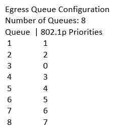
To view how queues are configured at egress ports, run the command “show qos queue-config”. The output will look like below. Note that CoS 0 corresponds to Queue 3, which is the default best-effort queue.


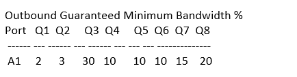
To view how port bandwidth is distributed among priority queues, issue the command “show bandwidth output ”. For example the command “show bandwidth output a1” will have the output as follows:


Above is the default bandwidth distribution among 8 queues. To change the guaranteed minimum bandwidth for Queue 3 to 20% and Queue 8 to 30% and the rest remain the same as default, use the command:

HP-5406zl(config)# interface a1 bandwidth-min output 2 3 20 10 10 10 15 30

When running the command “show bandwidth output a1” again, the output will look like this:


To monitor queues at an egress port (port A1 in the example below), use the commands:

HP-5406zl(config)# qos watch-queue a1
HP-5406zl(config)# show interface queues a1

The output will look like below. When the amount of outbound traffic on port A1 exceeds its capacity, dropped packets will start to appear in low priority queues.